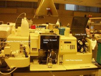
The image below shows a typical bench-top flame atomic spectrophotometer, which can be configured to work in either emission or absorption mode. This particular instrument can also be operated with a graphite furnace accessory. Click on the different parts of the instrument, or use the links below, for more details.

Parts of the AA: Light Sources | Burner/Spray Chamber | Graphite Furnace
Light Sources
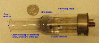
The key to making practical quantitative atomic absorption measurements was the development of a light source that had sufficiently high intensity over the very narrow wavelength range associated with each atomic electron energy transition. The hollow cathode lamp (HCL) achieves this by using a high-energy discharge to stimulate emission from the element of interest.
 As the name implies, the key component is a hollow cathode made or, or
containing, the element to be analysed. This is the cup-shaped metal
electrode in the centre of the image. A high dc potential is applied between
this cathode and an anode (in this case, a metallic ring surrounding and
slightly ahead of the cathode). This causes an inert filler gas (typically
neon) to ionize. The resulting high-energy particles bombard the surface of
the cathode, causing vaporization and excitation of the atoms within it.
The cup-shaped cathode contains this excited plasma, and directs the resulting
light emission out through the quartz window at the end (left-side of image).
The intensity of the emitted light is governed by the current flowing through
the lamp, but is limited by self-absorption at very high current densities.
HCLs are normally manufactured for a single element, although dual- and multi-
element lamps are available for common analyses such as calcium-magnesium
hardness or the characterisation of different types of steel.
[Image map] | [Top of Page] | [Burner/Spray Chamber] | [Graphite Furnace] | [Instruments]
Burner & Spray Chamber
When running in flame mode, solution samples are aspirated via the nebulizer into a spray chamber, before passing as an aerosol into the burner. During this process, the sample aerosol becomes mixed with fuel (commonly acetylene) and oxidant (typically air, but also nitrous oxide). The resulting high- temperature flame strips away the remaining solvent, breaks the sample components down into free atoms, and additionally stimulates atomic emission.
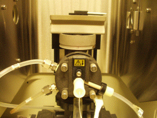
 This image shows the fuel, oxidant, and auxilary gas lines connecting
to the head of the nebulizer/spray chamber assembly. The nebulizer
consists of concentric steel tubes mounted in the front of the unit; gas
flows through the outer tube, causing a pressure drop across the inner
tube. This in turn draws the sample solution up through a small teflon
tube from the sample container. As the solution exits the inner tube, it
forms an aerosol. The spray chamber is constructed so that large drops
are either broken up or are trapped in the chamber, ultimately flowing
out of a drain positioned at the rear of the unit. The fine aerosol is
then swept up out of the spray chamber and into the burner. The burner can
be seen in the upper-rear of the flame compartment. The optical path
through this compartment is from right-to-left, just above the burner
slot and lengthwise through the flame. The burner height can be
adjusted in order to select a particular region of the flame for the
analysis.
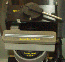
 This shows a top-down view of the burner, clearly showing the slot through
which the fuel/oxidant/sample aerosol emerges. In flame AAS, the measured
absorbance depends on the absorptivity of the element in question, the
concentration of that element in the flame (and therefore on its solution
concentration), and the optical pathlength through the flame. The light
from the flame region is collected on the left-side of this particular
instrument. Under certain circumstances, it is desireable to reduce the
optical pathlength. To this end, the burner head can also be rotated
about its vertical axis. Different burner heads (having different slot
sizes) are used for acetylene/air and acetylene/nitrous oxide flames,
since the latter is a much hotter flame. Flow controls also allow both
the total gas flow-rate and fuel-to-oxidant ratio to be varied. Gas
flow affects the aspiration rate and aerosol drop-size distribution,
while the fuel-oxidant ratio can influence chemical processes in the flame
that would otherwise reduce the sensitivity of the measurement.
[Image map] | [Top of Page] | [Light Sources] | [Graphite Furnace] | [Instruments]